Products
Manufacturers
Applications
The Arduino GIGA R1 WiFi bridges the gap between Arduino’s maker and professional spaces with a dual-core 32-bit microcontroller from STMicroelectronics, WiFi (802.11b/g/n @ 65 Mbps) and Bluetooth Low Energy connectivity, a secure element, both USB HID and Host capabilities via the USB-C programming/interfacing port and on-board USB A port, and an ample number of I/Os and interfacing options, including audio-visual interfaces.
At 53 x 101 mm, this is a mighty board that pushes the Arduino Mega and Due form factor to the next level with more I/Os and interfaces – some via two new headers that can be accessed from the top AND bottom sides of the board – bigger memory, and a wider 6-24 V input for direct interfacing with industry-standard power supplies. As a note, the Arduino GIGA uses 3.3-V logic, so direct I/O interfacing with 5-V systems should not be attempted.
Of the many applications this board can support, Arduino cites 3D printing, signal processing, robotics, and gaming as key markets, but the WiFi and Bluetooth connectivity in conjunction with Arduino Cloud means that it can be used for home automation and IoT applications as well.
The heart of the GIGA R1 WiFi is an STM32H747XI 32-bit microcontroller, which features a Cortex-M7 core with double-precision FPU and L1 cache running at up to 480 MHz, and a Cortex-M4 core with FPU running at up to 240 MHz. These are supported by 2 MB flash and 1 MB RAM and can be run completely separately to the extent that one core can be running MicroPython as the other runs traditional Arduino code.

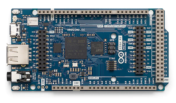
The basic pinout of the GIGA R1 WiFi is shown in the diagram above with a full pinout available here. The wired connections and interfaces of the GIGA R1 WiFi are as follows:
- USB-A connector for connecting memory sticks and peripherals such as mice or keyboards
- USB-C connector for power, programming, and use of the GIGA R1 WiFi as an HID for a computer
- 3.5-mm input-output jack connected to DAC0, DAC1 and A7
- 10-pin JTAG connector
- 20-pin Arducam camera connector
- Micro U.FL connector for external antenna
- 76x digital I/O pins
- 12x analogue input pins
- 13x PWM pins
- 2x analogue output pins
- 4x UART
- 3x I2C
- 2x SPI
- 1x CAN (external transceiver required)
- 3.3 V and 5 V output pins for logic reference and powering external boards
- Separate VRTC pin to power the RTC while the board is off
- OFF pin to turn the board off
For more information on Arduino’s most powerful board outside of their industrially certified PRO series, please consult this official datasheet.
Leveraging the new central connectors of the GIGA R1 WiFi, Arduino also offers the GIGA Display Shield for easy deployment of a GUI to any GIGA-R1-WiFi-based projects via the I2C bus. In addition to a 3.97” 480 x 800 px RGB screen supporting 16.7 million colours and 5-point touch-and-gesture control, this shield features a digital microphone, 6-axis IMU, and an Arducam connector. When the shield is in place, the user is still granted access to the 54 standard pins of the Arduino Mega/Due form factor, making this a convenient add-on for controlling your project.
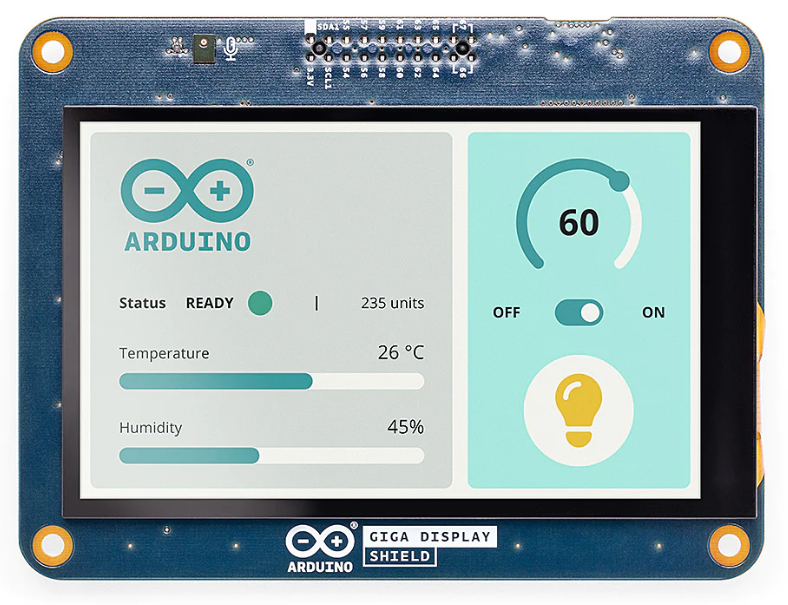
More information can be found in the Arduino GIGA Display Shield datasheet.
If you wish to evaluate the Arduino GIGA R1 WiFi for use in a commercial project with multiple units, fill out the form below, and ipXchange will put you in touch with our contact at Arduino for first-class service and pricing.